

How To Change Camera Lens On Iphone 6 Plus
Introduction
Follow the steps in this guide to supervene upon the rear-facing iSight camera in your iPhone 6s Plus.
Video Overview
-
-
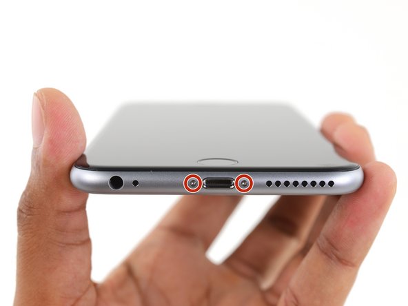
Power off your iPhone before beginning disassembly.
-
Remove the two 3.4 mm Pentalobe screws on either side of the Lightning port.
-
-
-
Optionally, apply mild rut to the lower border of the iPhone using an iOpener or hair dryer for about a minute.
-
-
-
Utilize a suction cup to the lower left corner of the display assembly.
-
-
-
Pull up on the suction loving cup with house, constant pressure to create a slight gap between the front console and rear case.
-
-
-
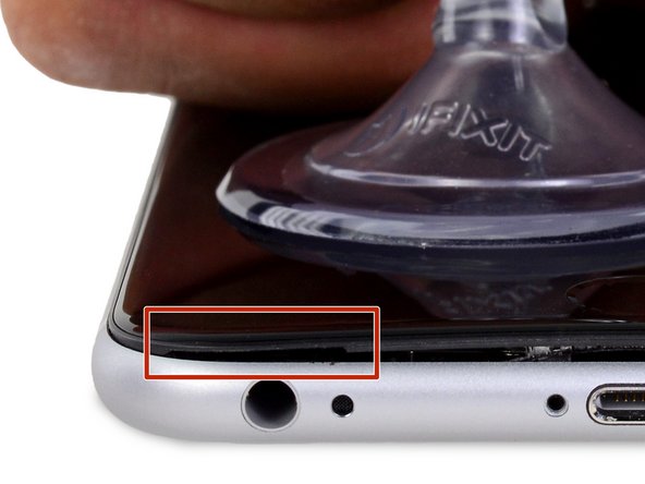
The safest place to pry from is the notch in the front panel above the headphone jack.
-
While still maintaining pressure on the suction cup, insert the flat tip of a spudger into the gap, directly above the headphone jack.
-
-
-
Twist the spudger to widen the gap between the front panel and the rear case.
-
-
-
While firmly pulling up on the suction cup, slide the edge of the spudger under the lesser left corner of the brandish.
-
-
-
Slide the tip of the spudger up the left side of the phone, between the forepart panel and the rear case.
-
-
-
Insert the flat tip of the spudger under the correct border of the display.
-
Slide the spudger upwards the correct side.
-
-
-
Apply a plastic opening tool to hold down the rear case while pulling up the suction cup to open the phone.
-
-
-
Pull up on the small nub on the suction loving cup to remove it from the display.
-
-
-
Gently grasp the display associates and lift it upward to open the phone, using the clips at the top of the front panel equally a swivel.
-
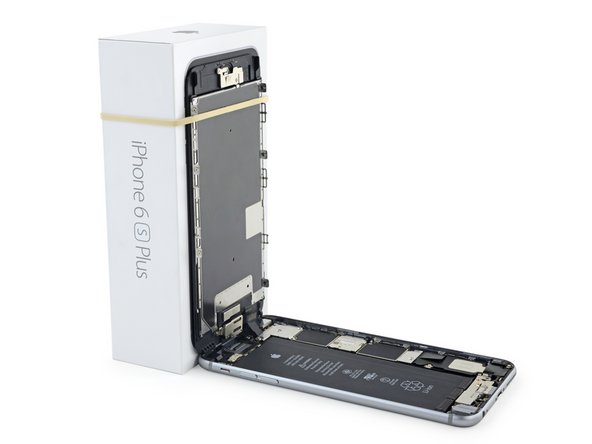
Open up the display to well-nigh a 90º angle, and lean it against something to keep information technology propped upward while you're working on the phone.
-
Add a rubber ring to go on the display securely in identify while you work. This prevents undue strain on the display cables.
-
-
-
Remove two Phillips screws securing the battery connector bracket to the logic board, of the following lengths:
-
I two.ix mm screw
-
One 2.3 mm spiral
-
-
-
Remove the bombardment connector bracket.
-
-
-
Use a spudger or a clean fingernail to disconnect the battery connector past prying it straight upward off the logic lath.
-
-
-
Bend the connector dorsum to ensure it doesn't make contact and power the iPhone on while yous're working on it.
-
-
-
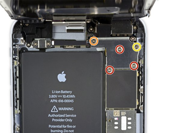
Remove the following Phillips screws:
-
Three i.three mm screws
-
One 1.6 mm screw
-
One 3.0 mm spiral
-
-
-
Remove the display cable bracket.
-
-
-
Use a plastic opening tool to disconnect the forepart-facing photographic camera and sensor cable connector.
-
-
-
Employ a plastic opening tool to disconnect the digitizer cable by prying information technology straight upwards from its socket on the logic board.
-
-
-
Disconnect the home button/fingerprint sensor cable past prying information technology straight up from its socket on the logic lath.
-
-
-
Remove the display assembly.
-
-
-
Peel up any tape covering the iSight photographic camera bracket screws.
-
-
-
Remove the following Phillips screws over the camera bracket:
-
One 1.nine mm spiral
-
One 2.4 mm screw
-
-
-
Remove the iSight photographic camera bracket.
-
-
-
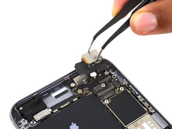
Disconnect the iSight camera connector from its socket on the logic board.
-
-
-
Insert the flat cease of the spudger between the iSight photographic camera and rear casing.
-
Gently pry the camera out from its housing.
-
-
-
Remove the iSight camera.
-


Conclusion
To reassemble your device, follow these instructions in reverse order.
Embed this guide
Choose a size and re-create the code below to embed this guide as a pocket-size widget on your site / forum.
Preview

Source: https://www.ifixit.com/Guide/iPhone+6s+Plus+iSight+Camera+Replacement/50934
Posted by: pruittsonsen82.blogspot.com
0 Response to "How To Change Camera Lens On Iphone 6 Plus"
Post a Comment